
Copyright © 1995 Walt Davis
http://www.waltdavis.net
This document begins by discussing the WMS-Library concepts as applied to an ideal called the World Modeling Scheme. Using an example to demonstrate the World Modeling Scheme we see how to simulate reality. We then move to a discussion of the world coordinate theory implemented by the World Modeling Scheme, not the entirety of the library, but the ideal. Following this is a more general discussion of the WMS-Library that reveals those applications not apparent while specifically discussing the World Modeling Scheme. Remaining parts of this chapter give reasons for project BUTTERFLY, what my goals are, the project requirements and assumptions, and some of the foreseen down falls.
Discussions delve heavily into the object-orient
paradigm and those theories of the paradigm that are built into the C++
language. It is recommended, that if the reader is not familiar with these
theories, for he/she to reference books pertaining to the subject of this
report; Object Oriented development. Theories involving computer graphics
are moderately exercised compared with that of the object-oriented paradigm.
However, some material on computer graphics may be useful in the reading
of this report.
|
|
Absolute Coordinate System |
|
|
Current Draw Color |
|
|
Current Graphics Port |
|
|
Graphic Object |
|
|
Graphics Port |
|
|
Graphics Port Buffer |
|
|
World Modeling Scheme |
|
|
Intermediate Coordinate System |
|
|
Primitive Drawing Method |
|
|
Normalized Device Coordinates |
|
|
Setup Coordinate System |
|
|
Space Access Status |
|
|
Space Mapping Status |
Attachment
Process by which a graphic
object is associated to and owned by a container graphic object and that
which provides the translation of the graphic object out of its coordinate
system into the coordinate system of the container graphic object.
Class
An Object-Oriented programming
data type possessing special abilities (encapsulation, polymorphism, and
inheritance) not present in traditional programming that defines a set
of objects that share common structure and behavior.
Classification
World Modeling Scheme process
by which the dissected parts of reality are classified to be one of the
three graphic object types shape, scene, or world.
Composition
(1) the declaration within
a class definition of a class type variable; (2) OOP container technology
from which objects are allocated form the heap and added to a list of objects
maintained by an already existing object; (3) the World Modeling construction
technique that provides the containment of graphic objects by a container
graphic via attachment.
Dissection
World Modeling Scheme process
by which reality is simplified by the breaking of it up into smaller and
smaller pieces that can be built individually.
Draw
Public method of a graphic
object class that defines the drawable substance of a graphic object.
Graphic Container
World Modeling Scheme graphic
object of scene or world class organ that contains other graphic objects
via attachment.
Graphic Object
OOP object that graphically
represents a specific aspect of reality, unique to the World Modeling Scheme,
autonomous, and classified as either a shape, scene, or world.
Inheritance
(1) The property of all
class types that allows a class to be defined which inherits all data and
method definitions that were previously defined by another class; (2) world
modeling construction technique by which graphic objects are given drawable
substance and that which provides the creation of new graphic object types
of shape, scene, or world class organ.
Instantiation
The declaration of a programming
variable of class type in the source code of a software program.
Method
Terminology coming from
Smalltalk, but used in C++ when referring to a member function.
Model Coding
World Modeling Scheme process
by which a world model is transformed into C++ software instructions that
create in computer memory a representation of its reality.
Model Rendering
World Modeling Scheme process
by which different aspects of a world model are rendered on the graphics
terminal through one or more graphics ports.
Object
(1) Any tangible and/or
visible thing, something that may be apprehended intellectually, or something
toward which thought or action is directed; (2) a variable having state,
behavior, its own private data and set of operations that can access that
data, and identity that's define by a class describing the structure and
behavior of like things.
Object-Oriented Programming
A method of software implementation
in which code is organized as cooperative collections of objects each representing
an instance of some class and whose classes are members of a hierarchy
of classes united by inheritance.
Primitive Drawing Method
A graphics primitive that's
a member of a graphic object type class which defines a piece of the graphic
objects drawable substance upon being placed within the graphic objects
method draw.
Private
Member data and methods
of a class that are private to the class object and only accessed by methods
belonging to the class from which the object was instantiated.
Public
Member data and methods
of a class that are public to the class object and accessible by entities
outside of the class definition.
Pure Virtual Function
An undefined class methods
that is specified pure using a pure-specifier in the function declaration
of the class definition, thus resulting in the class in which it was declared
becoming abstract.
Reality
Anything that can be represented
using two dimensonal images.
Scene
World Modeling Scheme container
graphic object possessing the ability to be composed of shapes and sub-scenes,
and representing the larger and more complex parts, not the undivided whole,
of the reality being simulated.
Shape
World Modeling Scheme graphic
object representing the atomic parts of reality.
World
World Modeling Scheme container
graphic object possessing the ability to be composed of shapes and sub-scenes
and representing the undivided whole of the reality being simulated.
Tformer
World Modeling Scheme object
that manages the manipulation of a transformation matrix which tracks all
transformations of a graphic object.
World Model
A model constructed using
the World Modeling Scheme that describes reality as a collection of graphic
objects and showing the relationships those graphic objects have to one
another.
World Modeling
World Modeling Scheme process
by which a world model is constructed using the dissected and then classified
parts of the reality being simulated.
World Modeling Scheme
A way of graphically simulating
reality using objects that simulate the individual parts making a reality
whole.
1.
Simulating Reality
The WMS-Library delivers to a programmer an assortment of tools allowing the writing of code that, when executed, will build and
graphically render two dimensional realities, i.e., two dimensional images.
The term world signifies a C++ object representing a world model. A world
model is a design developed using the World Modeling Scheme that represents
the undivided whole of reality. The World Modeling Scheme is a way of graphically
simulating reality using objects that simulate the individual parts making
a reality whole. With the World Modeling Scheme only a small semantic gap
between reality and the model will exist. An example of reality is my good
friend George, Figure 1. Using the World Modeling Scheme a simulation
is broken into the following processes:
of tools allowing the writing of code that, when executed, will build and
graphically render two dimensional realities, i.e., two dimensional images.
The term world signifies a C++ object representing a world model. A world
model is a design developed using the World Modeling Scheme that represents
the undivided whole of reality. The World Modeling Scheme is a way of graphically
simulating reality using objects that simulate the individual parts making
a reality whole. With the World Modeling Scheme only a small semantic gap
between reality and the model will exist. An example of reality is my good
friend George, Figure 1. Using the World Modeling Scheme a simulation
is broken into the following processes:
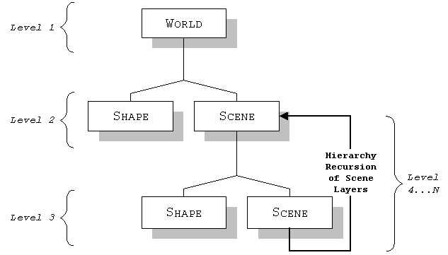
1.1.1.
Graphic Objects
Graphic objects are abstractions that represent specific
aspects of reality by defining a part of the reality's substance. Each
graphic object is unique to the World Modeling Scheme, autonomous, and
known as either a shape, scene, or world. The level of abstraction of a
graphic object is arbitrary. That is, each graphic object type has the
ability to represent equal definitions of a reality's substance. Their
difference, however, is in how the graphic object is constructed. Each
graphic object is provided by its corresponding class of the WMS-Library:
shape, scene, and world. As is, the shape, scene, and world class define
objects that have no drawable characteristic. Drawable substance of a graphic
object is defined by a programmer using class inheritance. Shapes, scenes,
a world and the use of derivation to give them substance is the underlying
principle of a world model and is that which gives rise to the name a World
Modeling Scheme.
1.1.3.
George's parts
Before dissecting and classifying George's parts lets
expand on the idea of a graphic object being an arbitrary abstraction defining
some aspect of the reality to be modeled. Using this definition, a graphic
object's abstraction is dependent upon one's interpretation of reality.
Nevertheless each graphic object type has a name that signifies something
different about the particular type: shape, scene, and world. The key understanding
of the World Modeling Scheme and its graphic objects is that a shape is
atomic, a scene is something more than a shape, and a world is everything.
Thus, upon one's Disssection of George we may find his reality consisting
of two 'ears', a 'face', two 'eyes', two 'pupils', a 'nose', and a 'mouth'.
Using the same notion we could then classify George's face as being the
only scene and all remaining parts to be shapes. However because an 'eye'
contains a 'pupil', one could have classified George's two eyes as being
scenes. Now we see that the abstractions of the graphic objects used in
the construction of a world model are dependent upon one's interpretation
of reality and are truly arbitrary.
1.2.1.
George's World Model
Building upon our Dissection and Classification of George's
parts (1.1. Dissection and Classification),
Figure 3 is a world model
of George. The model shows the whole of George’s reality as a collection
of those parts dissected and the relationship those parts have to one another.
Collectively these parts behave as one. Classified as either a world, scene,
or shape graphic object, each part defines a distinct aspect of George's
reality. From his world model we see all of George existing within one
world graphic object that's instantiated from the world class, his world
being composed of two graphic objects derived from the shape abstract plus
one from the scene class, and the scene graphic object being composed of
four shape graphic objects derived from the shape abstract.
One can extrapolate two reasons for choosing to derive George's face from the scene class; a 'face' has an outline and it consists of several additional parts. Both the scene and shape class are capable of defining the substance of a graphic object. However, unlike the scene class, the shape class has no means of containing other graphic objects. Thus, by deriving a new class from the scene class we are able to create a new graphic object type having all the qualities of the scene class and some drawable substance. In this case the drawable substance is a rectangular filled region.
This version of George's world model demonstrates three construction techniques. Special in definition when speaking of World Modeling, but general in nature to OOP, these construction techniques are called instantiation, composition, and derivation.
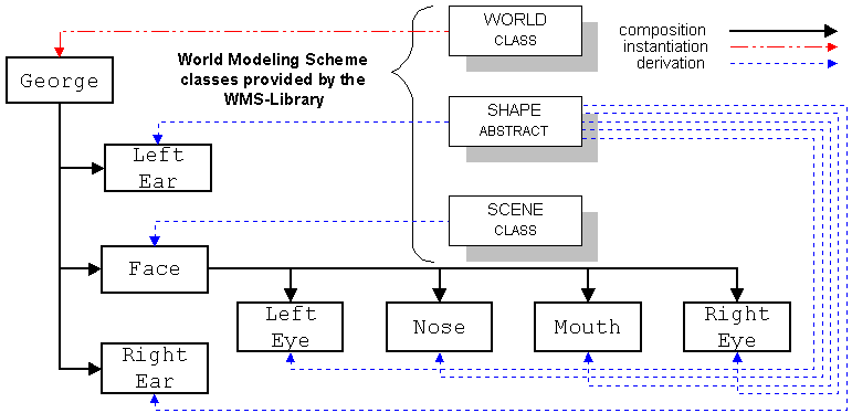
Composition is the containment of one or more graphic objects within another graphic object. There are two flavors of composition. The first flavor of composition is that of OOP container technology where an object is allocated from the heap and then added to an already existing object. The second flavor of composition is the aggregation of one or more objects within a class definition. When specifically speaking of World Modeling, composition refers to a modified version of OOP container technology. In general, the World Modeling idea of composition is somewhat simplistic in that a scene or world object or any object derived from them are the only graphic objects having the ability to contain graphic objects.
Derivation is the process of creating new class types using class inheritance. Inheritance is the property of all classes that allows a new class to be defined which inherits all data and method definitions that were previously defined by another class. This construction technique is by far the most complex, thus is the focus of 1.3. Model Coding. For now, simply remember that only classes directly or indirectly derived from the shape, scene, or world class are applicable to the construction of a world model.
1.2.3.
Variations to George's World Model
Now that we have a better understanding of World Modeling
and the three construction techniques, we are ready to look at some variations
to George's world model (figure 3). Using
instantiation we could have created eye and ear objects from preexisting
circle and rectangle class's that where derived from the shape abstract.
With composition we could have composed his world entirely of shape objects.
Or using derivation we could have derived a new world class called George.
The George class would be nothing more than a world class having its own
drawable substance. In this case the drawable substance is a rectangular
filled region representing an outline of George's face.
1.3.1.
The Shape Abstract
The abstract class shape is the most fundamental graphic
object. A solid grasp of its workings will lead to better understandings
of scene and world class usage, and from every aspect is the corner stone
to understanding the World Modeling Scheme. Three highlights of the abstract
class shape are:
(b) It has a pure virtual and public method called draw, who’s only purpose it to provide a means of giving a shape drawable substance.
(c) It's the primordial
base class from which all other graphic object class's are derived.
1.3.2.
Derivation
Derivation is the most powerful World Modeling technique.
In fact, without derivation there's no way of giving a graphic object its
own drawable substance. Previously, in 1.2.2.
The Three Construction Techniques, we found that to give
a shape graphic object drawable substance one derives a new class redefining
a member function draw that executes PDM calls and that the shape abstract
is the primordial base class of all graphic objects.
Because the shape abstract is a primordial base class within the heritage of the scene and world class, the scene and world class inherit all abilities of the shape abstract. However, unlike the shape abstract, the scene and world class (not derived scene and world classes) have redefined the function body of draw so that they have the may call the draw method of the graphic objects they contain.
Understanding how the scene and world class are derived and that they posses the abilities of the shape abstract, we can see that derived scene and world classes (classes derived from the scene and world class) are given drawable substance just as if deriving a shape class from the shape abstract. However, by deriving a new scene or world class and redefining draw just as would be done in deriving a new shape class, results in introducing a second draw within the same scope. Thus, if we want the derived graphic object class to have the same drawable substance as the base class from which it was derived as well as the drawable substance defined by the derived class, then we must explicitly call draw of the base class within draw method of the derived class.
Now we can formulate a clear definition for draw. The draw method of a graphic object is a public member of a derived graphic object class that when executed call's several PDMs and/or the draw method of the base graphic object class from which it was derived.
1.3.3.
Attachments
An attachment is the vehicle through which the composition
of shapes and scenes within a World Modeling Scheme container are accomplished.
This form of composition is an extremely modified version of traditional
OOP container technology where objects are simply added. With an attachment
we not only have the containment of one graphic object by another, but
we also have a translation of the object being attached out of its coordinate
system into the coordinate system of the container. In section 1.4.1.
Space, we will see that each graphic object has its own
coordinate system. For now, understand that a container object does not
perform the actual containment procedure. This is done by World Modeling
Scheme linker object.
Each attachment is carried out relative to a point within the rectangular boundary that defines the area of drawable substance of the graphic object being attached in addition to a point within the boundary of the container graphic object. Once attached, a graphic object becomes owned by and part of the container graphic object that it was attached to. Without deriving new graphic object types, only the shape and scene class graphic objects are attachable, and only scene and world class object types (called graphic containers) are able to contain other graphic objects.
1.3.4.
Linker Objects
A linker object facilitates the containment of graphic
objects by a container object via attachment. This is done by first associating
the linker object with a container object at which point the linker object
is able to perform the attachment by carrying out a coordinate system translation
of the object being attached and the memory management of the container
object.
There are two types of linker objects, one for attaching graphic objects to a scene object and another for attaching graphic objects to a world object. The use of linker objects is needed to prevent multiple friendship across the graphic object classes: shape, scene, and world, that would otherwise be needed in order for the graphic objects involved with the attachment to access each other's data members to obtain information needed for the coordinate system translation and memory management. Thus we only need two linker object types' requiring attachment knowledge of three graphic object types' verses having three graphic object types requiring attachment knowledge of each other. The accessibility of the graphic object data members is achieved through class friendship. This can be viewed as a two to one cardinality verses a three to three cardinality.
 1.3.5.
George's Pseudocode
1.3.5.
George's Pseudocode
Having an understanding of the shape abstract, attachments,
and the three construction techniques, we conclude our discussion of Model
Coding with an example Pseudocode of George's world model. Written in the
part's derivation section, but not shown in Figure 4, are the defining
bodies of the draw methods of each graphic object class. Also not shown
in this figure is the instantiation of linker objects. However, upon translation
to and execution of a block of C++ code, this pseudocode will create and
build in computer memory a model that represents George's reality. Once
this model is created in computer memory, George can then be observed from
many different aspects by the process of Model Rendering.
1.4.1. Space
Space is the name given to a module of traditional C
code provided by the WMS-Library that supplies the tools of an advanced
interface to the graphics terminal. The name space is used because this
module is that which allows the drawable substance of a graphic object
to be rendered. Without space a graphic object can not be seen, i.e., a
graphic object must have space in which to exist before existing.
Space provides several coordinate systems in which to navigate. Of these coordinate systems and the focus at this point in time is ACS (Absolute Coordinate System). In an ACS, coordinates specify the absolute position of a graphic object within space, that is, the final position within the overall region of space occupied by a world model. Thus, the ACS is the coordinate system used by the graphic object PDMs. Nevertheless, until becoming attached to a world model this system is implied and another system called SCS (Setup Coordinate System) is actually in play.
Space does not recognize the SCS. The SCS is specific to a graphic object. In fact, the SCS is actually an ACS to a graphic object. It's not until a graphic object is directly or indirectly attached to a world graphic object that the SCS becomes an ASC and then recognized by space. Both the SCS and the ASC are based on world coordinate theory which is discussed in section 2. World Coordinate Theory.
Graphic object PDM specified SCS positions are never permanently changed to ACS positions. SCS positions are actually transformed through a series of transformations built by attachments to an absolute position by a transformation performed within the graphic object PDMs. Once a graphic object PDM has carried out the transformation it then invokes the corresponding space graphics primitive, passing to it, the ACS positions, thus producing on the fly ACS positions upon execution of a graphic object's method draw.
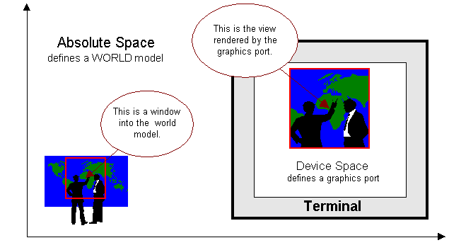
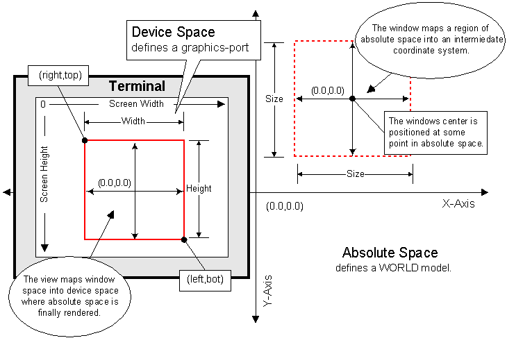
1.4.2.
The Graphics Port
Space graphics primitives (not primitive drawing methods)
are responsible for the mapping of continuous space into device space of
the graphics terminal by means of a graphics port. Graphics ports are the
eyes through which an observer can see images of a world model. Each graphics
port has its own window and view. The window is that portion of absolute
space being observed and the view is that portion of device space where
the windows image is rendered. The window can be positioned and moved anywhere
within a world, plus its size decreased or increased to give the effect
of a camera lens zooming in and out and the view can be positioned and
moved anywhere within the graphics terminal, plus its size decreased or
increased making the image smaller or larger. Figure 5, shows the
window to view mapping of a graphics port.
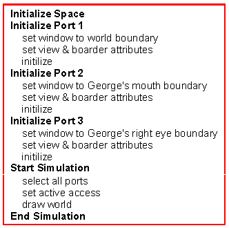 1.4.3.
Rendering George
1.4.3.
Rendering George
Writing code that renders images is rather simplistic
compared with that of the Model Coding or World Modeling. A graphics driver,
mode, and number of graphics ports is specified upon initialization of
space. Each graphics port is then focused on a specific region of the world
model to be rendered. Completing all necessary initializations, current
or active space access is chosen. Active access results in simultaneous
rendering of all active graphics ports while current access results in
rendering of a pre-selected port only. The Pseudocode listing of Figure
6 sets up three graphics ports that simultaneously render George's
entirety, look into his mouth, and inspect his right eye.
2.1.
Setup Coordinates
Setup coordinates refers to those positions passed as
formal argument values in the call of a PDM. Recall from section 1.3.1.
The Shape Abstract and 1.3.2. Derivation,
that the substance of a graphic object is created by the derivation of
a new graphic object class that uses the inherited PDMs of the base graphic
object class to define the function body of draw. This actually begins
by first sketching the lines or other characteristics that define the substance
image on a piece of graph paper. PDM calls corresponding to that which
is constructed on the graph paper and having formal argument values the
same as that found on the graph paper are then placed in the function body
of draw. Those coordinate values taken from the graph paper and
passed to the PDMs are the setup coordinates of a graphic object.
2.2.
Intermediate Coordinates
Intermediate coordinates specifically refer to the attachment
and transformation of a graphic object. Within the inheritance of each
graphic object is a transformation object called a tformer. The tformer
provides the functionality needed for the manipulation of a transformation
matrix that tracks all transformations of a graphic object. The representation
of these transformations by the matrix is that of an intermediate coordinate
system. The transformation matrix is thought of in this way because it
establishes the passage through which a graphic object transforms its setup
coordinates to absolute coordinates.
2.3.
Absolute Coordinates
Absolute coordinate, as stated in section 1.4.1.
Space, represent the absolute position of a graphic object in
space. Scene and shape graphic objects become absolute upon directly or
indirectly being attached to a world graphic object, until then their PDMs
are not able to render. Thus, the coordinate system of world graphic object
is always absolute.
2.4. Tformers
As discussed in section 2.2. Intermediate Coordinates,
each graphic object inherits a transformation object that is called a tformer
and the tformer manages a transformation matrix that tracks all transformation
of a graphic object. The tformers function within the World Modeling Scheme
is to provide an intermediate coordinate system through which a graphic
object's substance is transformed from a setup coordinate system to an
absolute coordinate system. Thus, the intermediate coordinate system represents
the translation of graphic object out of its coordinate system into the
coordinate system of the container object that it's attached to as well
as non-attachment transformation that the graphic object may have gone
through, but to this point we have yet to explore the transformation capabilities
of a tformer, how a linker object uses a tformer in an attachment, or the
possibilities of transforming a graphic object other than attachment .
2.4.1.
Tformer Transformations
A tformer has member functions for translation, scaling,
rotation, reflections, shears, and composition of any sequence of the previous
operations. All the operations with the exception of translation are carried
out relative to an arbitrary point. Rotations may be in the clockwise or
counter clockwise direction. The shearing operations are y-shear and x-shear.
And among the reflection operations is reflection in the y-axis, x-axis,
origin, y = x, and y = -x. Compositions of these operations are achieved
with the overloaded multiplication and negation operators. With the multiplication
operator multiplying on the left is pre-multiplication and multiplying
on the right is post-multiplication.
2.4.2.
Attachments
During an attachment a linker object has access to both
the tformer of the graphic object being attached and the tformer of the
container object in which the graphic object is attached to. As discussed
in section 1.3.4. Linker Objects, this
accessibility is provided by class friendship. A linker object carries
out an attachment as follows:
(b) Transform the graphic object tformer with that of the container graphic object's tformer, preserving all previous transformations. This is done using matrix multiplication.
(c) Transform the
graphic object tformers of any graphic objects contained within the graphic
object being attached with that of the container graphic object's tformer
just as was done with the graphic object being attached.
2.5.
Graphics Port Geometry
Figure 7 is an example of the window to view mapping
of a graphics port as applied to absolute space. This mapping is based
on world coordinate theory and should serve as a better example of the
theory than trying to show how the theory carries through the tranformations
executed in the coding of George's world model.
3.1.
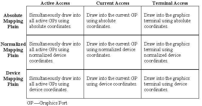
The Three Plains of Drawing
Of the three drawing plains, each has two attributes
determining the outcome of a space graphics primitive call: mapping (absolute,
normalized, and device) and access (active, current, and terminal). Mapping
refers to a specific plain, distinguished by the coordinate system used
to specify the formal arguments of a graphics primitive. When using an
absolute or normalized drawing plain the arguments of a graphics primitive
are transformed into device coordinates. The device plain assumes that
the formal arguments are already in device form. For each plain the access
determines whether or not a graphics primitive maps into all active graphics
ports, the current graphics port, or directly to the graphics terminal.
Graphic object PDMs always operate in the absolute plain and conform to
world coordinate theory. Each plain and its access has their own CP (current
position) and CC (current draw color). Figure 8 sumarizes the three
drawing plains and their modes of access.
3.2.
Normalized Device Coordinates
NDC (Normalized Device Coordinates) represent positions
within the graphics terminal or the graphics port in a device independent
manner. Such a coordinate system describes the view surface of the graphics
terminal as a set of real numbers ranging from 0 to 1 in both the X and
Y direction, with the origin in the upper left hand corner. When using
terminal access the these coordinates represent device positions within
the terminal ranging from 0 to screen width in the X direction and 0 to
screen height in the Y direction. When using active or current access these
coordinates represent device positions within the graphics port view ranging
from 0 to view-width in the X direction and 0 to view-height in the Y direction.
3.3.
One Theoretical Application
I have conjured an example pertaining to George
that demonstrates the power of space singelton PDMs combined with World
Modeling Scheme PDMs. To get things rolling, lets add a shape graphic object
to George's world model. This shape is that of a push button labeled open
and is arbitrarily attached to George's world object. The shape is constructed
with the space singelton PDMs using a normalized drawing plain and terminal
access so that the button is always rendered in the upper left hand corner
of the graphics terminal. Also associated to this shape is another world
model separate that of George and a mouse interrupt type object. The new
world model simulates George's a